stra57
Member

 Offline Offline
Posts: 31
|
 |
« Reply #3045 on: January 29, 2024, 02:56:03 PM » |
|
Dear Nigel,
I managed to download the dukumentation from dropbox.
I would like to build the speed controller.
Is it possible to buy a PCB or its Gerber file.
I would be interested in that, because I read the whole forum and there was no mention of the turntable engine.
Which engine can it be used for?
Best Regards
András
|
|
|
|
|
 Logged
|
|
|
|
analogadikt
Administrator
Member
 Offline
Age: 59
Location: India
Posts: 5,246
|
|
« Reply #3046 on: January 29, 2024, 05:28:38 PM » |
|
Dear Nigel,
I managed to download the dukumentation from dropbox.
I would like to build the speed controller.
1)
Is it possible to buy a PCB or its Gerber file.
I would be interested in that,
2)
because I read the whole forum and there was no mention of the turntable engine.
Which engine can it be used for?
Best Regards
András
Please note 1) Nigel already replied about this here. https://www.lencoheaven.net/forum/index.php?topic=43917.msg525349#msg5253492) Well , if you read the whole forum, then you should have understood that this speed controller was designed for the Lenco idler drive motor and people are using it for that purpose and also similar motors like the Garrard 301/401. Also there is a discussion about the suitability to some other motors. It is the few posts just before the link above. You have posted there , so you should have seen that?  It appears that you want to build a controller for this motor. https://www.lencoheaven.net/forum/index.php?topic=44052.msg525800#msg525800Elsewhere you make this comment Its name is Mechlabor SL 102 for studio. Made in Hungary
Driver is too complicated. Motor Papst perfect. tonearm EMT clone.
If the Papst motor is three phase and the controller has failed , then Nigel's controller is not a suitable replacement.
Someone on diyaudio forums (analogue source section) has made three phase controller. That might be suitable for your requirements . Please check on that. Please also do note that I shall not be able search for the exact link , if you are interested, it would be better to search yourself. Regards, Anwesh |
|
|
|
« Last Edit: January 29, 2024, 05:49:26 PM by analogadikt »
|
Logged
|
|
|
|
fthedj
Member
Offline
Posts: 8
|
|
« Reply #3047 on: February 16, 2024, 12:22:51 AM » |
|
Hi Nigel - I'm in the US and am using the specified Triad transformers.
I have worked my way through your assembly instructions successfully until I get to this point:
Part 6, Page 5
"Connect the multimeter probes across the pads marked “+11V5” and “0V” on the bottom right hand corner of the PCB. Switch on the AC supply again. The voltage reading should be close to 11.5V (between 11.3 and 11.7V)"
I get no reading on my multimeter at this step. On the step before this (testing voltage across D4 and D6) I get a reading of 63V
Can you help?
Thanks!
Dave
|
|
|
|
|
Logged
|
|
|
|
nigel
Member
Offline
Age: 58
Location: Isle of Wight, UK, Europe
Posts: 4,137
|
|
« Reply #3048 on: February 16, 2024, 03:06:15 AM » |
|
Hi Dave, OK, that's a strange one  First and most obvious question - Are R30 and R31 fitted and soldered correctly? Carefully check : - Regulator U2 is the correct way round (metal tab facing towards the centre of the PCB) - Capacitor C9 is the correct way round - Resistors R18, R19 are fitted and the correct value - check soldering on all of the above Assuming that all looks good, then next thing to try - put the black/negative probe of the multimeter on the "0V" pad again and put the red/positive probe on the left hand end of D4. You should read approx 32V there. Assuming that's OK, then leave the black probe on the "0V" pad and move the red probe to the end of D11, furthest from the 0V pad (D11 is next to U2). You should read approx 32V there also. Let me know what you find and we'll go from there .... |
|
|
|
|
Logged
|
Tofu-eating Guardian reader.
|
|
|
fthedj
Member
Offline
Posts: 8
|
|
« Reply #3049 on: February 16, 2024, 04:51:19 AM » |
|
Hi Nigel - thanks so much for the help!
Here is where I'm at after following the above suggestions.
1. R30/R31 - the solder on one leg of R30 was questionable, so I reflowed it
2. U2 installed the correct way
3. C9 installed the correct way
4. R18/R19 fitted properly and correct values
after this, I checked voltages per your suggestions
1. Part 6, Page 4/5 - checked voltage across D4 and D6 = 75.3V
2. Part 6, Page 5 - checked voltage across 115V and 0V pads = 3.2V
3. per your suggestion in post 3050 - voltage across 0V pad and D4 = 37.6V
- voltage across 0V pad and D11 = 37.6V
Thanks!
Dave
|
|
|
|
|
Logged
|
|
|
|
nigel
Member
Offline
Age: 58
Location: Isle of Wight, UK, Europe
Posts: 4,137
|
|
« Reply #3050 on: February 16, 2024, 12:04:32 PM » |
|
Hi Dave, Hmm, well that all looks OK, except this - 2. Part 6, Page 5 - checked voltage across 115V and 0V pads = 3.2V
This is beginning to look like U2 is faulty. Very unusual, but not unheard of. OK, one more test - Measure the voltage across R18 - should be very close to 1.25V What does it measure there? If you're able to post a photo of the topside and underside of the PCB in this area, that might be helpful  |
|
|
|
|
Logged
|
Tofu-eating Guardian reader.
|
|
|
fthedj
Member
Offline
Posts: 8
|
|
« Reply #3051 on: February 16, 2024, 05:10:33 PM » |
|
Hi Nigel, I get a reading of 0V across R18. Here are the photos you requested   Thanks! Dave |
|
|
|
|
Logged
|
|
|
|
nigel
Member
Offline
Age: 58
Location: Isle of Wight, UK, Europe
Posts: 4,137
|
|
« Reply #3052 on: February 17, 2024, 03:30:15 AM » |
|
Hi Dave, Well, I don't see anything wrong with your PCB, but the fact that there's no voltage at all across R18 doesn't make much sense. An (external) short between pins 1 & 2 of the regulator would give us no voltage across R18, but the output would then sit at near enough the input voltage (i.e. ~ 37V). So, it can't be that. R19 disconnected (or open circuit) would give us no current through R18 and hence no voltage across it, but that would also leave the output sitting at the input voltage, so it can't be that either. I think this only leaves 2 possible scenarios - 1. There is no connection between R18 and the centre pin of U2 (although it certainly looks OK) 2. U2 is faulty To narrow this down, try the following - Measure voltage between either end of R18 and the "0V" pad. If this is consistent with previous measurements, then you should see around 3.2V at both ends. If that's what you see, then all connections are good. That would leave U2 faulty as the only explanation, I think  |
|
|
|
|
Logged
|
Tofu-eating Guardian reader.
|
|
|
fthedj
Member
Offline
Posts: 8
|
|
« Reply #3053 on: February 18, 2024, 06:19:17 PM » |
|
Hi Nigel,
I checked the voltage across both ends of R18 and the 0V tab and on both ends I get a result of 3.1V
It sounds like a bad regulator, so I'll order another one, install it and then will update this thread with my results one way or the other
Thanks again for all the support!
Dave
|
|
|
|
|
Logged
|
|
|
|
nigel
Member
Offline
Age: 58
Location: Isle of Wight, UK, Europe
Posts: 4,137
|
|
« Reply #3054 on: February 18, 2024, 11:49:51 PM » |
|
Hi Dave, OK, will await your findings  |
|
|
|
|
Logged
|
Tofu-eating Guardian reader.
|
|
|
fthedj
Member
Offline
Posts: 8
|
|
« Reply #3055 on: February 20, 2024, 08:58:27 PM » |
|
Hi Nigel -
I removed and replaced the U2 regulator and retested across the 0V and 115V test points and my resulting voltage was spot on at 11.5V
Thanks so much for your help!
Dave
|
|
|
|
|
Logged
|
|
|
|
nigel
Member
Offline
Age: 58
Location: Isle of Wight, UK, Europe
Posts: 4,137
|
|
« Reply #3056 on: February 20, 2024, 09:38:32 PM » |
|
Excellent  |
|
|
|
|
Logged
|
Tofu-eating Guardian reader.
|
|
|
|
gninnam
|
|
« Reply #3057 on: April 28, 2024, 04:29:00 PM » |
|
Hi everyone and I hope someone can point me in the right direction. Purchased a pre-built NSC a few months back and the person who built it said it was never used so unknown if it will work (suggested that just the pots on the oscillator board need trimming so the output PSU was not connected). Connected my spectrum analyzer and every thing appears to check out and measured the voltages for the PSU across the diodes and all good, plus the voltage at the oscillator (11.55 V) so everything seems to check. So, to the funnies. 1. There are LED's fitted next to the trim pots but no matter which speed is selected, no light. 2. The unit has a display to show output voltage and moving this, you can see the voltage increase/decrease but moving the trim pots, nothing happens to the read out? A few pics. _NSC2.png?width=1920&height=1080&fit=bounds) 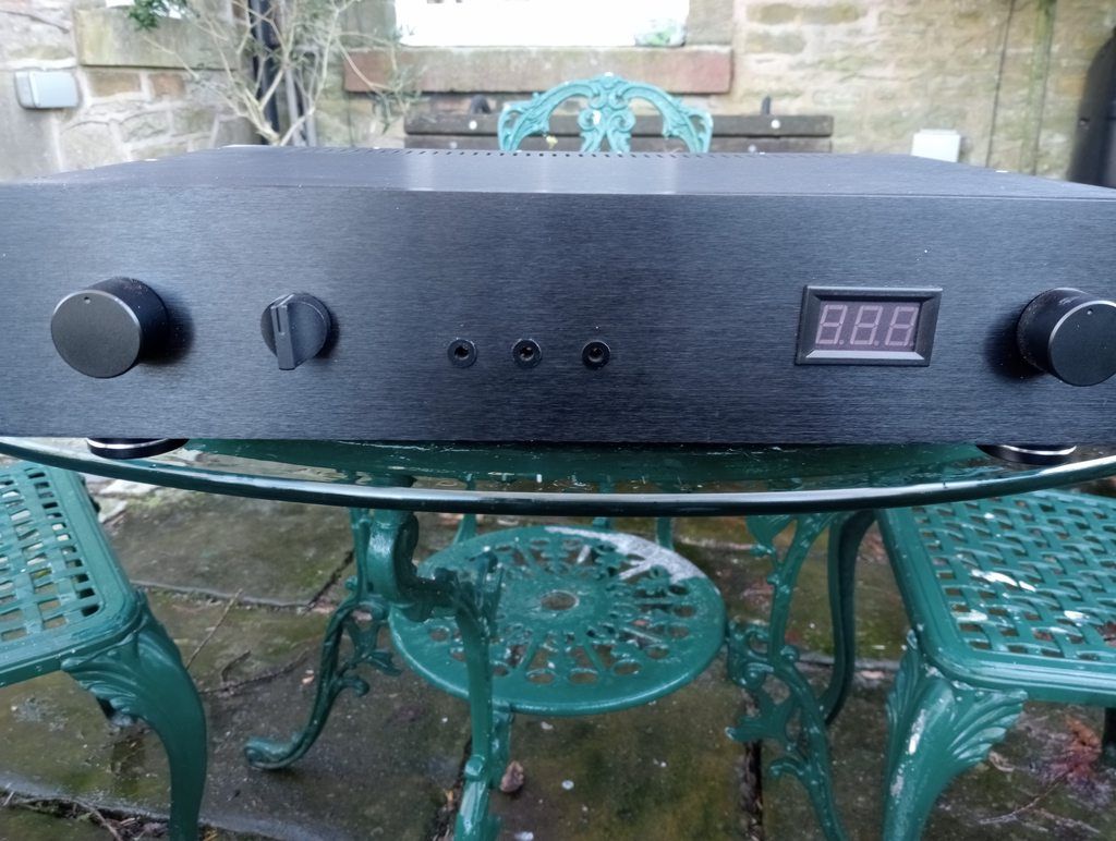 _20240428_153803.png?width=1920&height=1080&fit=bounds) (As you change the speed selector on the front of the PSU the amplitude on the scope changes which is good) _20240428_153809.png?width=1920&height=1080&fit=bounds) 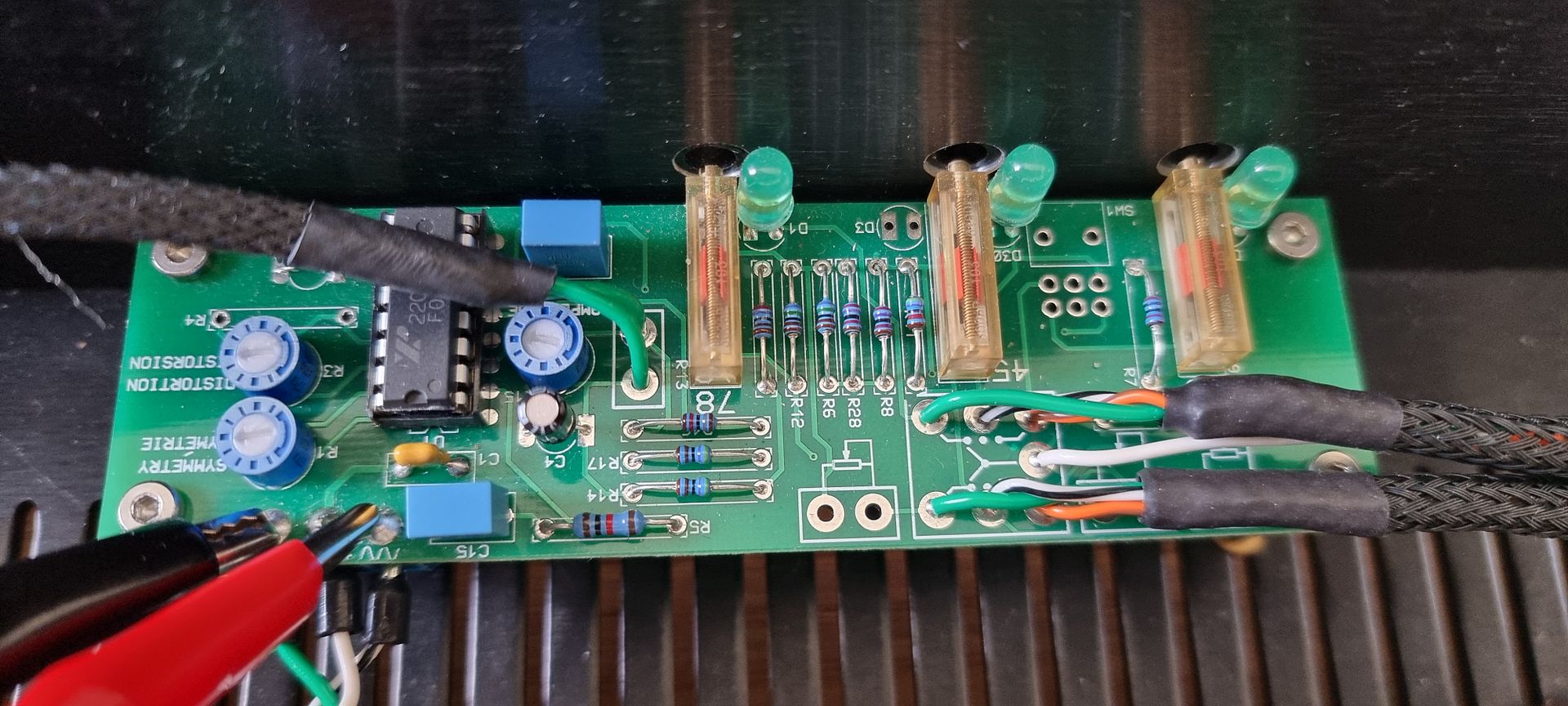 Many thanks for your advice and help |
|
|
|
|
Logged
|
Name: Andy
Location: UK (Leeds)
|
|
|
mrca
Member
Offline
Posts: 12
|
|
« Reply #3058 on: April 30, 2024, 11:42:06 PM » |
|
Hi everyone and I hope someone can point me in the right direction. So, to the funnies. 2. The unit has a display to show output voltage and moving this, you can see the voltage increase/decrease but moving the trim pots, nothing happens to the read out? Many thanks for your advice and help G'day Andy My understanding is that adjusting the Oscillator Board Trim Pots changes the frequency, not the voltage? The amplitude pot changes the voltage? Regards Colin |
|
|
|
« Last Edit: May 01, 2024, 09:52:23 AM by mrca »
|
Logged
|
|
|
|
nigel
Member
Offline
Age: 58
Location: Isle of Wight, UK, Europe
Posts: 4,137
|
|
« Reply #3059 on: May 01, 2024, 01:09:59 PM » |
|
Sorry Andy, just typed you a long reply and it disappeared ('bad gateway' error or something)  Will get back to you shortly. |
|
|
|
|
Logged
|
Tofu-eating Guardian reader.
|
|
|
|

