Turbon
Member

 Offline Offline
Age: 65
Location: Skåne - Sweden
Posts: 864
Audiosmith
|
 |
« Reply #30 on: January 24, 2014, 09:45:52 AM » |
|
Thanks for clarifying this Gene.
I'll see what you people come up with. Really interesting even if it doesn't make any major impact on my setup.
Regards
|
|
|
|
|
 Logged
|
Turbon  |
|
|
|
RCAguy
|
|
« Reply #31 on: January 24, 2014, 02:09:28 PM » |
|
Hi Robin !! Ok.....that means..... I could push any of this lil switches 3 times a day for one year !!  Lot of work to change my cartridges 3 times every day.....    Serious.... I'm aware about it...... (technician) It's all about to find the right load for (a new) cartridge... And to have different values......with different kinds of capacitators/resistors...... Once you have the right load....... the switches remains in it's position ! But thanks for the hint ! Roger that. (I know you've heard it before.) Can a "technician" unsolder as well as solder? Why not buy the C substitution PCB below for $9.99, remove as many caps as you need to, install a bunch of discs over the range we're interested in, and you're a lot further along toward your goal than a complete implementation starting with a single DIP switch? I've bought often from this seller, who also has a resistor substitution board using header jumpers. http://www.ebay.com/itm/1nF-to-9999nF-Step-1nF-Four-Decade-Programmable-Capacitor-Board-SUK9712C-/370987974865?_trksid=p2047675.l2557&ssPageName=STRK%3AMEWAX%3AIT&nma=true&si=vOS0ccMD09BpltcSPW9Rq2JFVls%253D&orig_cvip=true&rt=nc |
|
|
|
« Last Edit: January 24, 2014, 06:17:04 PM by RCAguy »
|
Logged
|
|
|
|
|
RCAguy
|
|
« Reply #32 on: January 24, 2014, 02:23:43 PM » |
|
Yes and of course there are other approaches/topologies to circumvent or minimise Miller effect (e.g. cascode), but I suspect that very many commercial phono stages don't use them on cost grounds and many DIY designs don't on grounds of complexity ....  Exactly, this is the reason why, out of professional need as well as frustration with choices available, I invested months designing and building my own, but it's what I do (plus for me the fun/satisfaction). Even so motivated, it took a year part time! But for the rest of us, maybe we need to broaden our investigation and develop a list (probably a short one!) of good-performing, affordable off-the-shelf phono stages? We'd first need a consensus on the criteria, including which circuit topologies to favor - not a little daunting. |
|
|
|
« Last Edit: January 24, 2014, 05:31:30 PM by RCAguy »
|
Logged
|
|
|
|
|
RCAguy
|
|
« Reply #33 on: January 24, 2014, 03:03:05 PM » |
|
...I'd like an "elevator speech" about these questions:
1. What do they mean by "null?"
2. How did they go about measuring the capacitance of the input circuits?
Phono load impedance is a different subject that I think is even less common than the capacitance issue! I don't know where to begin about that, and I just noticed that the subject of the table is "impedance," but they specified "resistance." Which? 1) "Null" is measuring a minimum signal with an oscilloscope at the Vout terminal. But this circuit can be much simplified to just the two variable components: you can delete R & R (that cuts V1 in half) and the summation stage that outputs Vout by connecting a dual-trace scope to V1 & V2, scaling to double sensitivity the channel whose probe is attached at V2, and setting the scope to ch1 minus ch2 to view the difference signal, watching for a squarewave minimum as Ca in particular is adjusted (Ra will by 47kΩ unless the preamp has a different R-load). 2) Once your scope is showing a minimum wave that is once again squared, your preamp's input C is the value of the variable Ca. (E.g. Mouser #659-GME50301 "trimmer capacitor" 65~320pF $8.15; or if you're technical, modify the C substitution PCB in post #32 above.) To measure your preamp's input C: Use a quasi-bridge like the BAS circuit, consisting in its simplest form, if a 2-channel oscilloscope is available, of a square wave generator set to output -40dB, Ra = 47kΩ resistor (or variable potentiometer if your preamp uses a different R-load), and variable capacitor Ca, as above. Insert the "device under test" (DUT) preamp inside the BAS diagram's circle - the preamp's input impedance becomes the bottom arm of a complex voltage divider that you want to equal the top arm in terms of both R & C, so they more-or-less cancel, forming the "null." Once you see that minimum and a re-squared waveform, then your answer for the preamp's C-load is the value of your variable Ca. Then of course you need a C-meter or bridge to measure Ca out of circuit to know what that is. If you used the C-substitution box, add up directly the capacitances you engaged for the C-load measurement. Voila3) As Gene points out, the preamp input "impedance" in the context of this thread is just resistive AND capacitive load on the cart. For most, the R value is 47kOhm - if not, see "Caveats" in post #36 below. The desired total C load includes the non-negligible parallel capacitance of the cabling. For example with Stanton carts, we'd want as a reference point to adjust either the cable length or add a selected C to the preamp's input C to total ˜275pF (+10%/-0% for a 681, +20%/-0% for an 881). |
|
|
|
« Last Edit: January 29, 2014, 03:59:49 AM by RCAguy »
|
Logged
|
|
|
|
|
RCAguy
|
|
« Reply #34 on: January 24, 2014, 03:47:40 PM » |
|
...While soldering yesterday the comments made by Wout were rumbling around in my head. In particular, his remark flagging up Robin´s comment about nothing much happening above 5KHz, and that effect of capacitance in these cartridges occurred well above this level. So, maybe the switch is changing the cartridge output but it just isn't audible. Another explanation as to why I didn't hear a difference is that the overall capacitance of the system is already higher that the optimal value of 275pf and adding more on top of this already overloaded setup isn't resulting in an audible change... Just to clarify what I have said (post#22 of this thread): I often see little/nothing >8kHz in pop music, although up to the full range exists naturally in most acoustic classical/jazz discs. And the C-loading of in particular Stanton 681 & 881 carts affects significantly from below 3kHz and up - see post #36 at http://www.lencoheaven.net/forum/index.php?topic=14975.30 So the effect of changing C-loading should be audible if you can hear >3kHz. Particularly audible are peaks in response which should be avoided; dips are more benign and therefore the desirable compromise if one must be made. (And you're correct to ensure that your external selector is not being overwhelmed by a much higher existing capacitance.) First things first: determine your starting C-load seen by the cartridge? You have to measure it, or at least find any published data from cable and preamp makers, but even then "Trust, but verify." If it is lower than the cart maker wants, say 275pF for Stantons (assuming 47kΩ load R), your job is easy: lengthen your phono cables, or add capacitance along the way, at the headshell if not inside the preamp. On the other hand if it's more than 10~20% too high (e.g. >325pF for Stanton 681 or >375 for Stanton 881 visually interpolated from post #36 above), you need to do at least one of the following: shorten the phono cabling according to x=C to lose / cable C/ft; replace the phono cable with better quality with lower pF/ft - 10pF/ft video coax (not RF coax for cable TV) is not expensive; inside the preamp remove the existing capacitor across the input jack and replace it with your newly calculated value. |
|
|
|
« Last Edit: January 24, 2014, 06:31:09 PM by RCAguy »
|
Logged
|
|
|
|
ecosprog
Member
Offline
Age: 63
Location: Up the mountain, Spain
Posts: 2,429

|
|
« Reply #35 on: January 24, 2014, 04:06:34 PM » |
|
Just to clarify what I have said: I often see little/nothing >8kHz in pop music, although up to the full range exists naturally in most acoustic classical/jazz discs. And the C-loading of in particular Stanton 681 & 881 carts affects significantly from below 3kHz and up - see post #36 at http://www.lencoheaven.net/forum/index.php?topic=14975.30 So the effect of changing C-loading should be audible if you can hear >3kHz. Particularly audible are peaks in response which should be avoided; dips are more benign and therefore the desirable compromise if one must be made. (And your correct to ensure that your external selector is not being overwhelmed by a much higher existing capacitance.) First things first: what is your starting C-load? You have to measure it, or at least trust any published data from cable and preamp makers. I "trust, but verify." If it is lower than the cart maker wants, your job is easy - lengthen your phono cables, or add capacitance along the way, if not inside the preamp. On the other hand if it's more than 10 or 20% high (e.g. >325pF for Stanton 681 or >375 for Stanton 881), you need to do at least one of the following: shorten the phono cabling; replace the phono cable with better quality (lower pF/ft - not expensive); inside the preamp remove the existing capacitor across the input jack and replace it with a calculated new one. As mentioned in my previous post, a meter is on its way. However, I think it´s unlikely that I am over 275pf because I know what the phono stage is adding (100pf), and I know what the cable is adding (65pf/m). I have 70cm of cable from the base of the tonearm to the phono stage so that adds roughly 46pf. Then there is the stuff in the box and the wiring in the tonearm, the sum of which is unlikely to add another 129pf to the overall capacitance. As I have already mentioned a capacitance meter is on it way and, once in hand, I will be able to measure the exact capacitance of the full run from cartridge to phono stage. What surprised me was that there really wasn´t any change that would make me sit up and take note. Perhaps my expectations were too high, and I was expecting a miracle that simply wasn´t ever going to happen. I will persist with this trial and see what the figures show. |
|
|
|
|
Logged
|
|
|
|
|
RCAguy
|
|
« Reply #36 on: January 24, 2014, 05:21:18 PM » |
|
Reese - we look fwd to your C-meter results. Meanwhile, what is your preamp's R-load? It would scale your C-loading by a reciprocal amount.
Caveat - if you know or suspect that your preamp's load resistance might not be 47kΩ? The wide assortment of R-load in consumer products above suggests to me manufacturers' attempts to compensate for imperfections due to cost-cutting, implying optimal results with only the cartridge they used for prototyping! Verify your preamp's R-load first by: reading the preamp's specs; opening the preamp and reading the resistor's value; or measuring Ra with the variable resistance of the BAS bridge.
If your R-load is different from 47kΩ, your job determining a proper C-load is harder, but not impossible, either using the frequency sweep of a good test disc, or as follows. With an ACVM at the preamp's output, set up a "simulation" of your cartridge by substituting it with a signal generator, connected in series with an external inductor and resistor equal to the cartridge coil's L & R, and injecting ~10mV (-40dBv) at the headshell with the cart disconnected. Then sweep the range 1~20kHz with the generator and adjust C-load for flattest preamp output. The other channel should be a close match, but you can tweak that C-load if needed. Much easier is just to change each channel's resistors inside the preamp to the de facto standard 47kΩ!
A further caveat might be the inductance of a ferrite bead inserted in the preamp's input wiring to suppress RF noise - I have to investigate that, as I use them. (And as none of this matters for low impedance carts, chalk up yet another point or two for the MC team - it's frustrating, I know, for those of us using MM/MI.)
|
|
|
|
« Last Edit: January 24, 2014, 06:52:07 PM by RCAguy »
|
Logged
|
|
|
|
ecosprog
Member
Offline
Age: 63
Location: Up the mountain, Spain
Posts: 2,429
|
|
« Reply #37 on: January 24, 2014, 05:46:48 PM » |
|
Reese - we look fwd to your C-meter results. Meanwhile, what is your preamp's R-load? It would scale your C-loading by a reciprocal amount. See my amended post #35 above for more about that complication. (And yet another point for the MC team - it's frustrating, I know, for those of us using MM/MI.)
My phone stage is a Lehmann Black Cube if that's of interest. It has three settings for resistance, 47k, 100ohm, and a user defined setting. The latter allows you to fit whatever value your heart desires. I tend to leave it on the 47k setting as I use step up transformers for my MC cartridges, and I don't need to change this when I switch over to a MM/MI cartridge. |
|
|
|
|
Logged
|
|
|
|
richard
Member
 Offline
Location: Southeast Tennessee, USA
Posts: 7,797
|
|
« Reply #38 on: January 24, 2014, 08:32:57 PM » |
|
Just passing through briefly, again. Reese, when measuring your cables, don't forget to include the arm wiring. Typically, this is the place of greatest capacitance along the route. And that's because the wires have to be little, flexible, and that they're usually surrounded by large amount of grounded stuff (the arm itself). Have no fear about my computer progress. I'm setting up one or two "legacy" Windows XP machines which will probably be kept off-line, just to access my prior files. And, following up on our previous thread, I'm setting up a couple of computers to run Linux, which will probably be Mint (I'm just not sure which desktop, yet). You were a great help, by the way. I've been working on the free Supplement to the Stanton/Pickering Handbook, and my Supplement work is on the computer with the virus!  The book itself, however, prints from the machine that I'm writing on right now. And that's OK. |
|
|
|
|
Logged
|
Richard Steinfeld
Author of The Handbook for Stanton and Pickering Phonograph Cartridges and Styli.
|
|
|
Wout
Administrator
Member
 Offline
Location: Rotterdam, Netherlands
Posts: 4,378
|
|
« Reply #39 on: January 25, 2014, 12:08:23 AM » |
|
Reese, I wonder if you use an user defined load R of 100KΩ and then play with your cap box, you might hear differences.
Higher R -> less damping of the resonant peak (if any).
|
|
|
|
|
Logged
|
Wout
|
|
|
fetteler
Member
Offline
Age: 68
Location: Staffordshire Moorlands UK
Posts: 4,539
|
|
« Reply #40 on: January 25, 2014, 01:04:58 AM » |
|
Steve, it's not me who has a virus; it's my main computer that is indisposed big-time. I figure that it's going to take two solid days of work to fix this. Thank you for the links, but organic medicine doesn't work on robots, you know. Richard, I'm so awfully embarrassed by my idiocy that I couldn't bear to see my post displayed - mocking me in my childish stupidity - so I've deleted it. I don't think the sense of the thread suffers at all. Steve. |
|
|
|
« Last Edit: January 25, 2014, 01:34:53 PM by fetteler »
|
Logged
|
Have nothing in your house that you do not know to be useful, or believe to be beautiful.
I try to spell correctly - sometimes the dyslexia wnis!
|
|
|
ecosprog
Member
Offline
Age: 63
Location: Up the mountain, Spain
Posts: 2,429
|
|
« Reply #41 on: January 25, 2014, 08:11:20 AM » |
|
Reese, I wonder if you use an user defined load R of 100KΩ and then play with your cap box, you might hear differences.
Higher R -> less damping of the resonant peak (if any).
Good suggestion Wout. I had avoided doing this because I really wanted to see what would happen using the standard impedance found in a MM phono stage. I was listening to some classical guitar last night and I think I may have heard a difference while flipping through the different values on my new switch. In the end I settled on 47pf as sounding best. Of course this could have all be due to a couple of glasses of local red wine. I will have a go tonight using the 100 Ohm setting on the phono stage. |
|
|
|
|
Logged
|
|
|
|
|
|
mimoser
Member
Offline
Age: 57
Location: Krems / Wachau / Austria
Posts: 274
|
|
« Reply #43 on: January 25, 2014, 11:41:36 AM » |
|
there is too much tech-speak as well as too much argot in there to be fun to translate, but if needs must I could have a go …
btw do any of you have some suggestions regarding low capacitance connects RCA-RCA on a budget?
Michael
|
|
|
|
|
Logged
|
|
|
|
Rotsch
Member
Offline
Age: 61
Location: Germany "@the lost west"
Posts: 3,542
Follow the white rabbit.....
|
|
« Reply #44 on: January 25, 2014, 05:40:00 PM » |
|
Yup....Rob !!  I was thinking bout something like that........... We call it .... Widerstandsdekade = Resistor-decade Kondensatordekade= Capaci...... The professional "decades" are really expensive... But if i make it "DIY"....i would be much more cheapo But......you know.... DIY starts.......with small thingies....like this.....  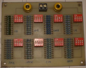 And mostly end like this...... 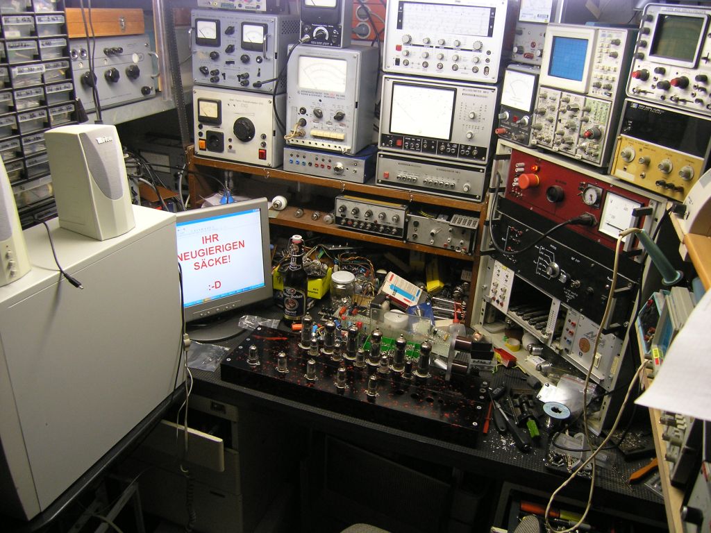 Have a nice WE !! |
|
|
|
|
Logged
|
Roger  "To play a wrong note is insignificant. To play without passion is inexcusable." "To play a wrong note is insignificant. To play without passion is inexcusable." -Ludwig Van Beethoven
|
|
|
|

