floppybootstomp
Member

 Offline Offline
Age: 74
Location: Greenwich
Posts: 3,679
|
 |
« Reply #405 on: April 16, 2025, 02:32:08 PM » |
|
Yes! I can't see any benefit in having the PSU turned on and the RIAA amplifier turned off.
Agreed. |
|
|
|
|
 Logged
|
My real name is Tony
|
|
|
|
niclaspa
|
|
« Reply #406 on: April 16, 2025, 02:57:14 PM » |
|
Also, you would need to switch both the high tension and the heater supply off. Leaving the heaters on without high tension will make the tubes go bad fast.
|
|
|
|
|
Logged
|
Niclas
Ernst ist das Leben, heiter ist die Kunst
|
|
|
|
damiena
|
|
« Reply #407 on: April 16, 2025, 03:27:44 PM » |
|
Thanks all. Sorry for the foolish questions, I should have realised all this myself. The guidance is greatly appreciated.
I was looking for a switch that could switch both, but was slowly dawning on me it would need to be something humongous!
And of course, I’d end up half the time turning off the phono but not bothering to turn off the PSU, which isn’t good.
|
|
|
|
|
Logged
|
Damien
I must create a system or be enslaved by another man's...
|
|
|
|
damiena
|
|
« Reply #408 on: April 22, 2025, 01:54:53 PM » |
|
Back on the job of putting Vlads phono together, and of course there are more questions! This time it’s the polarity of the signal inputs and outputs. How do I tell what is signal ground and what is live? I tried looking up if the footprint markings on the PCB mean anything, but haven’t found anything useful. Both output and input rectangles have a little extra rectangular tab shape on one side - does this mean anything? Also each input shape has a 1 in it (both channels), but the output markings only have a 1 in one channel - are these numbers meant to mean anything?   |
|
|
|
|
Logged
|
Damien
I must create a system or be enslaved by another man's...
|
|
|
stratokaster83
Member
Offline
Age: 41
Location: Dublin, Ireland
Posts: 2,711
When I see mommy, I feel like a mummy
|
|
« Reply #409 on: April 22, 2025, 02:06:19 PM » |
|
if you have a multimeter, you can simply check for continuity between the pads and the ground. I would assume that the pads that are closest to the ground pad are ground, simply because it makes sense layout-wise
|
|
|
|
|
Logged
|
And those with no sandwiches,
Please get off the bus.
|
|
|
|
damiena
|
|
« Reply #410 on: April 22, 2025, 02:10:00 PM » |
|
if you have a multimeter, you can simply check for continuity between the pads and the ground. I would assume that the pads that are closest to the ground pad are ground, simply because it makes sense layout-wise
Nice one! Thank you  |
|
|
|
|
Logged
|
Damien
I must create a system or be enslaved by another man's...
|
|
|
vlad1980
Member
Offline
Location: Romania
Posts: 150
|
|
« Reply #411 on: April 22, 2025, 02:28:36 PM » |
|
See this image for the input and output. 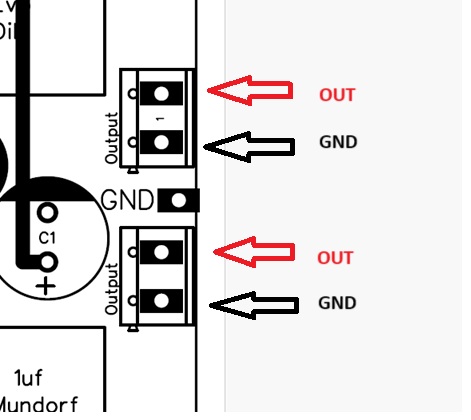 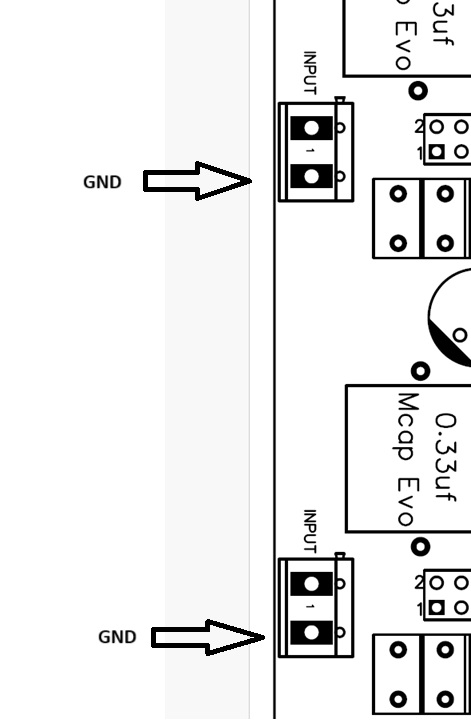 Back on the job of putting Vlads phono together, and of course there are more questions! This time it’s the polarity of the signal inputs and outputs. How do I tell what is signal ground and what is live? I tried looking up if the footprint markings on the PCB mean anything, but haven’t found anything useful. Both output and input rectangles have a little extra rectangular tab shape on one side - does this mean anything? Also each input shape has a 1 in it (both channels), but the output markings only have a 1 in one channel - are these numbers meant to mean anything? |
|
|
|
|
Logged
|
|
|
|
|
damiena
|
|
« Reply #412 on: April 23, 2025, 03:09:21 PM » |
|
See this image for the input and output. Prefect, thanks Vlad. |
|
|
|
|
Logged
|
Damien
I must create a system or be enslaved by another man's...
|
|
|
|
damiena
|
|
« Reply #413 on: May 21, 2025, 06:55:40 PM » |
|
I've been away, building cases, but I'm back now  My phono stage works! Sounds great. However the high voltage supply is a bit high - 330v DC. I've been recommended to add a 10k resistor to tame it. Sooo... If the supply voltage is 330v and I want 300v going to the anode then Vs - Va = 330 -300 = 30v drop From the PCF802 datasheet (not sure if I'm reading it correctly however) Pentode anode current is 6mA and the Triode 3.5mA Therefore: Iap = 6mA Iat = 3.5mA Can I add Iap + Iat to get total current? i.e Ia = Iap + Iat = 6 + 3.5 = 9.5mA ? Therefore to drop by 30v -> R = (Vs - Va)/Ia = 30v/9.5mA = 3158 ohms = approx. 3K and Power dissipation would be P = (Vs-Va)^2/R = 285mW However if I use If use R=10k that looks like a 95v drop :- Vs-Va = R * Ia = 95v and power dissipation would be: P = 95^2/10k = 902.5 mW Either way, if calculations are correct, I need at least a 500mW resistor if it's 3k ohms, and a 1W resistor if it's 10k ohms... Are my calculations correct? |
|
|
|
|
Logged
|
Damien
I must create a system or be enslaved by another man's...
|
|
|
|
niclaspa
|
|
« Reply #414 on: May 21, 2025, 07:02:01 PM » |
|
I'm not sure if you want to use one resistor for each channel or one common resistor for both. If you are going for one resistor per channel then your calculations are correct. Using a resistor rating 3 times the power dissipated is a rule of thumb. So go for a 1 W resistor.
|
|
|
|
|
Logged
|
Niclas
Ernst ist das Leben, heiter ist die Kunst
|
|
|
|
damiena
|
|
« Reply #415 on: May 21, 2025, 07:20:46 PM » |
|
I'm not sure if you want to use one resistor for each channel or one common resistor for both. If you are going for one resistor per channel then your calculations are correct. Using a resistor rating 3 times the power dissipated is a rule of thumb. So go for a 1 W resistor.
Thank you Niclas. My electrical theory is a little rusty, as is my maths. So I appreciate the sense check. For the 10k ohm resistor though 3x would be 3W..? |
|
|
|
|
Logged
|
Damien
I must create a system or be enslaved by another man's...
|
|
|
|
niclaspa
|
|
« Reply #416 on: May 21, 2025, 08:25:23 PM » |
|
For the 10k ohm resistor though 3x would be 3W..? Yes, but that would bring down the voltage too much. |
|
|
|
|
Logged
|
Niclas
Ernst ist das Leben, heiter ist die Kunst
|
|
|
simon
Member
Offline
Posts: 164
|
|
« Reply #417 on: May 21, 2025, 08:33:31 PM » |
|
If you have 1kOm resistor, just put it in series between 330 V
and the phono stage. Mesure voltage drop over the resitor .
This way you will find exact consumation of phono stage,
U drop (V) / R =1000 (Ohm) = I (A)
After that , you can estimate exact resitor to get 300V in real world.
|
|
|
|
|
Logged
|
|
|
|
|
damiena
|
|
« Reply #418 on: May 21, 2025, 08:48:09 PM » |
|
If you have 1kOm resistor, just put it in series between 330 V
and the phono stage. Mesure voltage drop over the resitor .
This way you will find exact consumation of phono stage,
U drop (V) / R =1000 (Ohm) = I (A)
After that , you can estimate exact resitor to get 300V in real world.
That’s smart. I don’t have any 1W 10ks. The best I could do is 5 250mw in parallel to approximate. Messy. Or I have a 20k 2.2W resistor and know I have another, just can’t find it. I like the pre-analysis experiment. I’ll drop what voltage I can with what I have that’s specced appropriate. |
|
|
|
|
Logged
|
Damien
I must create a system or be enslaved by another man's...
|
|
|
simon
Member
Offline
Posts: 164
|
|
« Reply #419 on: May 21, 2025, 09:04:10 PM » |
|
10 kOm in series is too much ( I think ) For the pre-analysis , don't need power resistor, and You can use ANY kind that you have - 10 Ohm, 100 Ohms, other value ( but 10 kOm  ) Just : Voltage drop / Value of resistor = Real Current |
|
|
|
|
Logged
|
|
|
|
|

